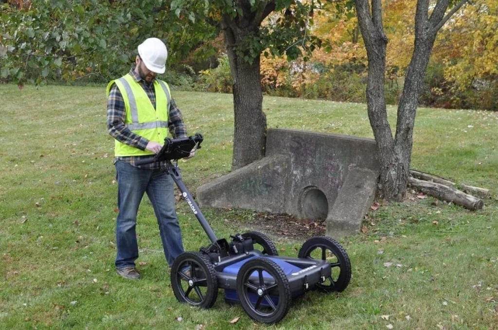

When you need answers beneath the surface, deep ground penetrating radar (GPR) gives you a non-destructive way to see patterns, follow routes, and flag subsurface anomalies before you dig. The core decision that shapes every result is the frequency you use. Higher frequencies reveal fine detail near the surface; lower frequencies reach greater penetration depth with less detail. The right setting depends on your targets (underground utilities, subsurface structures, or large buried objects), soil conditions, and how quickly you need to interpret GPR surveys on site.
Ground penetrating radar works by sending radar pulses into the ground and recording the reflected signal at material boundaries. Those reflections become the GPR data you read as profiles or depth-based views.
Ground Penetrating Radar Theory in Plain Language
How GPR works
A GPR antenna transmits short bursts of electromagnetic energy into the ground. Where dielectric properties change, part of the radar energy returns to the antenna and is logged as a profile you can review immediately. The basic physics are simple: stronger contrasts produce stronger reflections; weaker contrasts produce subtler returns that benefit from tighter coverage and smart visualization.
Frequency vs. depth capabilities
In practice, higher frequencies give high resolution at shallow depth, while lower frequencies deliver more depth penetration with less detail. That’s why concrete assessments lean high-frequency, and deep corridor reconnaissance leans low-frequency. Cart-style systems typically support a frequency range that spans both ends for different jobs and soils.
Factors That Control Penetration Depth (Beyond Frequency)
Frequency is only half the story. The medium you scan controls how far radar waves travel and how much they attenuate or scatter.
- Electrical conductivity and signal attenuation: clay soils, saline or salt-contaminated zones, and wet ground increase losses. Dry sand generally supports deeper penetration.
- Heterogeneous conditions: signal scattering rises in rocky fills and mixed backfill, softening hyperbolas and horizons.
- Target size/orientation: larger or continuous features are easier to follow than small, isolated point reflectors, especially at depth.
- Different velocities: changes in material velocity can skew a depth scale unless you anchor interpretations with site knowledge or checks at known depth.
These conditions explain why deep ground penetrating radar is generally non-intuitive at first glance: the same antenna can behave differently across a single site as soils change.
When to Choose Low-Frequency GPR (Deeper Look-Ahead)
Long-corridor utilities and broad reconnaissance
For utility locating across roads, rights-of-way, or plant corridors, low-frequency antennas help you keep a continuous trace over distance. The priority here is continuity and penetration depth, not fine detail at the surface.
Large features and deep screening
Low-frequency settings help screen for large subsurface features and buried objects such as underground storage tanks or void-like responses in complex backfill. They’re also useful for reconnaissance near grave sites or unmarked graves, where the goal is to identify broad pattern changes before tighter follow-up.
Conductive or difficult soils
In high conductivity materials and wet clay soils, moving down in frequency can maintain visibility where high-frequency responses fade. Adjust line spacing, slow down, and collect perpendiculars to produce results under tough soil conditions.
When to Choose High-Frequency GPR (High Resolution Near Surface)
Concrete and near-surface detail
High-frequency antennas resolve small subsurface objects and thin layers. They are ideal for concrete work where you need fine detail around reinforcing patterns or near-surface interfaces. In consistent media like concrete, high-frequency responses are crisp and easy to interpret in the field.
Precision mark-outs
Along a construction project edge or shallow corridor, high-frequency profiles make it easier to pick the apex of hyperbolas, follow a short run, and mark with confidence. The trade-off is shallower penetration; plan your passes accordingly.
Reading and Using the Data in the Field
Recognizing patterns
During acquisition, a GPR unit (antenna plus control unit) plots continuous profiles. Point reflectors create hyperbolas; continuous layer changes show as horizons. The apex of a hyperbola aligns with a target’s centerline, which is why operators mark that point on the ground surface when tracing a linear feature.
Calibrating expectations
Use repeat lines or a check at known depth to confirm your penetration depth. Because different subsurface materials have different velocities, a quick verification keeps your depth picks honest. Where patterns are ambiguous, collect cross-sections (perpendicular passes). These simple steps help you interpret GPR surveys with more confidence.
Field Workflow: Matching Frequency to the Job
Define survey objectives
State your targets first: underground utilities, subsurface structures, or deeper subsurface anomalies. Objectives drive frequency and antenna choice.
Choose antenna frequencies and line spacing
Select high vs. low frequency based on target size/depth, then set line spacing to match the risk and resolution you need. For linear targets, start with corridor lines; if anything is unclear, add a grid or perpendicular passes.
Document and export
When GPS is used during collection, you can display and save coordinates with the data and export points for mapping in CAD/GIS or Google Earth, which is useful for revisiting routes without returning to the site.
Example Frequency Choices by Scenario
Low-frequency leaning
- Tracing deep water lines and other corridors over long distances.
- Recon for large buried objects, broad anomalies, or potential underground storage tanks.
- Variable backfill and rocky soils where scattering blurs high-frequency detail.
High-frequency leaning
- Detail around the near surface where clarity is critical.
- Small, shallow features in consistent media; thin layers, interfaces, or tight structural checks.
- Sites where precise mark-outs improve safety and speed.
Limits to Keep in Mind (Soils, Conductivity, Moisture)
Even with the best frequency choice, electrical conductivity sets a hard ceiling on depth. Wet clays and saline zones absorb energy quickly; dry sand and uniform fills help pulses travel farther. In heterogeneous conditions, expect more signal scattering and softer returns. Adapt the plan: diversify frequency, tighten coverage, and lean on cross-lines to build a clearer picture.
Choosing Deep Ground Penetrating Radar Settings with Confidence
Picking the right settings for deep ground penetrating radar comes down to three steps: match antenna frequencies to your depth and detail needs, adapt for soil and moisture, and verify in the field with smart line plans and cross-checks. The underlying ground penetrating radar theory is consistent, but the site dictates how you apply it. With a clear objective and a practical workflow, GPR turns profiles into decisions you can act on.