
Ground-penetrating radar, or GPR, is a powerful and effective way to locate, map and measure underground objects, structures and materials. Countless professionals across numerous industries rely on it for accurate, non-destructive data collection. And for those professionals who require 3D representations of subsurface areas, GPR is the most reliable and accurate solution available. Continue reading and visit our site and learn more about GPR and how it works.
That said, any kind of 3D imaging requires a large amount of data. The information required to depict a 3D object is exponentially higher than what’s required with a 2D option. As such, using GPR to perform 3D subsurface imaging requires more time than a typical survey. More importantly, it takes careful planning and thoughtful execution. Done haphazardly, a 3D survey might result in data that’s inaccurate and simply won’t provide a good representation of the survey site.
Fortunately, the proper approach isn’t difficult to follow. We’ve provided this guide to help you assess your site, plan your survey and execute it flawlessly. While it’s geared to helping our customers with their US Radar GPR products, it should prove helpful to anyone conducting a 3D survey with GPR technology.
How to Conduct a 3D Survey: A Framework

A good 3D survey follows a framework. This helps you make the right decisions and lays the foundation to ensure your survey collects accurate data. If you’re aiming to create 3D depth slices and peak maps that accurately depict the survey site, this framework ensures you get the data you need to do so.
Keep in mind, these surveys take more time than a 2D survey. As such, a 3D survey requires many more lines. A good general rule is to plan for at least twice as many lines, but adequate data accuracy may require more than that.
Preparation is key for a 3D survey. You simply won’t get usable results without methodically planning your grid. You’ll need to plan your approach based on the survey’s needs, determine your starting point and measure and mark every line.
Tip: Keep in mind, 3D imaging builds on the data provided with 2D imaging. High-quality 3D data requires high-quality 2D data. In general, if you can’t spot a target clearly in 2D mode, it won’t show up in 3D mode either. Difficult targets tend to be easier to locate in 2D.
Setting Up a Grid
Properly setting up your grid lays the foundation for the success of your 3D survey. Any guesswork during this stage results in bad data. You need to measure and physically mark the grid. If you’re surveying hard material, use chalk. With softer material, marker flags or spray paint is best.
The first step is setting up your zero line. This is the basis for the rest of your grid. From here, you’ll determine your starting corner. This indicates the starting point for your survey and the direction your survey travels in. The display on your GPR unit indicates the first axis you’ll scan with numbered lines. If you’re using a second axis, it’s indicated with lettered lines.
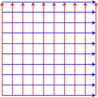
Next, you’ll select a grid pattern to use. When you start your survey, it’s critical to follow this pattern. If you deviate from the grid pattern, you’ll end up with inaccurate data and your 3D models won’t match the survey site.
Tip: The zig-zag pattern isn’t recommended for 3D surveys. Accurate 3D data depends on an accurate physical grid, which is difficult to obtain using the zig-zag pattern. While it’s possible to nudge and reverse lines in the software, you’ll need to know how much the data was off in order to do so.
Selecting a Grid’s Line Separation
Generally speaking, the more lines acquired, the better the quality of the 3D survey. This takes time, however, and we’re often faced with how to balance survey quality with time constraints. Because of this, it’s important to understand the variables that impact the quality of your data.
⦁ For large objects with less detail, wider survey lines are adequate.
⦁ Smaller, higher detail objects require tighter line separation.
⦁ Unfavorable soil conditions require more data for accuracy, which means tighter lines.
⦁ Favorable soil conditions provide better accuracy, which means you may be able to space lines wider.
If you’re uncertain about these variables, the best approach is to simply use the width of your radar antenna.
Next, you’ll need to mark your grid. On your zero line, use a tape measure to determine line separation and mark each survey line with chalk, spray paint or a marker flag. If you’re surveying both axes, which is recommended, mark the zero line here as well. With your grid measured and marked, you’re ready to begin your survey.
Tip: While there are edge cases where surveying a single axis may provide adequate data, it’s highly recommended that you scan both axes for a 3D survey. Again, the more data you collect, the more accurate your 3D models are.
Conducting a 3D Survey

With your grid set up and all points marked, you’re ready to begin. The first step is configuring your US Radar GPR unit. To begin, click on the map area or the 3D button in the new scan menu. Select your grid pattern and your line separation measurements.
Fixed and Flex Grids

When you’re configuring your GPR unit to begin conducting your survey, you’ll have to choose between a fixed grid or a flex grid. These are worth looking at in a little more detail because they can change your approach and the resulting data significantly.
Fixed grids create data lines with consistent lengths and produce 3D renderings in cube-line shapes. If you select a fixed grid, you’ll need to enter a distance for your scan. If you choose this option, the GPR’s software stops scanning once you reach that distance and prompts you to start the next line.
Flex grids let you run each survey line as far as needed. While you still need to start from a precise axis, this setting lets you have different shapes and jagged edges on the ends of your survey lines. This can be useful in asymmetrical environments where obstructions interfere with a square grid.
This option also allows you to conduct free-form or S-shaped surveys. This involves collecting a single line and moving the radar in the pattern you want to collect. It’s also possible to collect more than one line in a free-form survey, though you’ll need very precise positioning equipment such as RTK GPS.
Tip: Most failed free-form surveys result from not collecting in a tight enough pattern. When you open your data in 3D, you can choose to use the GPS coordinates to display it in the pattern it was collected.
Surveying
Starting from your zero line, press the play button and push the cart forward to the end of the survey line. If you’re using a fixed grid, the software stops scanning automatically. For flex grids, you’ll stop the line manually. If you make a mistake while scanning, you can discard the line and try again. Keep in mind, however, you can only do this once per line. Once you’re done scanning, save the line and move back to the zero line.
Bring the unit back to the zero line and move to the next line on the axis. If you properly saved the previous line, the software selects the next line for you. Press play and repeat the process until you’ve completed all lines on the axis.
If you’re using a fixed grid, the software automatically switches to the second axis once you save the last line of the first axis. Once you’ve collected all the lines on the first axis, the software switches to the second lettered line axis. If you’re using a flex grid, you’ll need to select the second axis manually.
And that’s all there is to it. Once you’ve completed all the lines, you can finish the survey and begin interpreting and processing your data. If you’ve collected on two axes, you can view your data and 3D models or slices.
Successful 3D Imaging With US Radar

A lot of operators and professionals depend on accurate 3D subsurface imaging to perform their job effectively. Regardless of the specific solution those individuals use, they all leverage GPR technology to get the job done. There simply isn’t a better approach to imaging underground objects and materials in three dimensions. Whether you’re experienced with GPR technology and interested in a new solution or you’re considering it as a new tool in your workflow, we’d like to help.
At US Radar, we’ve pushed the limits on what ground-penetrating radar technology can do. For almost three decades, we’ve designed and engineered innovative GPR solutions for professionals in construction, engineering and archeology, among others. We’ve also built a worldwide network of representatives to support our customers and help them get the most of their GPR solutions. To find out how we can help you, get in touch with us today.